ASME/ANSI B16.5 Lap Joint Flanges
Our company provides ASME/ANSI B16.5 Lap Joint Flanges.
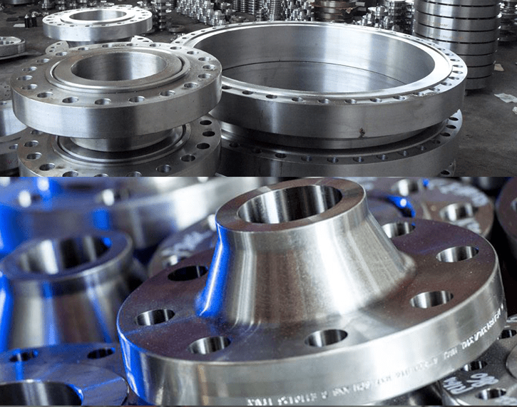
The lap joint flange is designed to be used with a stub end, which is a short piece of pipe that has a welded-on flange. The lap joint flange slides over the stub end and is then bolted in place. It is commonly used in applications where frequent disassembly and cleaning are required, such as in food processing or pharmaceutical industries.

lewis Liu
sales Manager
ASME/ANSI B16.5 Lap Joint Flanges
ASME/ANSI B16.5 Class 150 Lap Joint Flanges
(a)All dimensions are in inches.
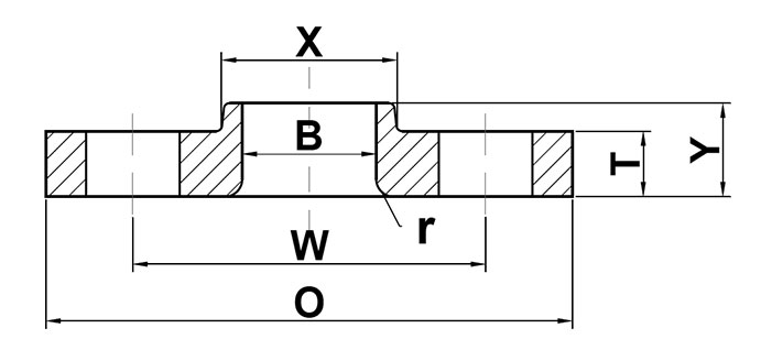
| Nominal Pipe Size | Outside Diameter (O) | Bolt Circle (W) | Radius (r) | Number of Holes | Diameter of Holes | Hub Diameter (X) | Bore (B) | Thickness (T) | Length Thru Hub (Y) | Approximate Weight (lbs) |
|---|---|---|---|---|---|---|---|---|---|---|
| 1/2 | 3.50 | 2.38 | 0.12 | 4 | 0.62 | 1.19 | 0.90 | 0.44 | 0.62 | 1 |
| 3/4 | 3.88 | 2.75 | 0.12 | 4 | 0.62 | 1.50 | 1.11 | 0.50 | 0.62 | 2 |
| 1 | 4.25 | 3.12 | 0.12 | 4 | 0.62 | 1.94 | 1.36 | 0.56 | 0.69 | 2 |
| 1 1/4 | 4.62 | 3.50 | 0.19 | 4 | 0.62 | 2.31 | 1.70 | 0.62 | 0.81 | 3 |
| 1 1/2 | 5.00 | 3.88 | 0.25 | 4 | 0.62 | 2.56 | 1.95 | 0.69 | 0.88 | 3 |
| 2 | 6.00 | 4.75 | 0.31 | 4 | 0.75 | 3.06 | 2.44 | 0.75 | 1.00 | 5 |
| 2 1/2 | 7.00 | 5.50 | 0.31 | 4 | 0.75 | 3.56 | 2.97 | 0.88 | 1.12 | 7 |
| 3 | 7.50 | 6.00 | 0.38 | 4 | 0.75 | 4.25 | 3.60 | 0.94 | 1.19 | 8 |
| 3 1/2 | 8.50 | 7.00 | 0.38 | 8 | 0.75 | 4.81 | 4.10 | 0.94 | 1.25 | 11 |
| 4 | 9.00 | 7.50 | 0.44 | 8 | 0.75 | 5.31 | 4.60 | 0.94 | 1.31 | 13 |
| 5 | 10.00 | 8.50 | 0.44 | 8 | 0.88 | 6.44 | 5.69 | 0.94 | 1.44 | 15 |
| 6 | 11.00 | 9.50 | 0.50 | 8 | 0.88 | 7.56 | 6.75 | 1.00 | 1.56 | 19 |
| 8 | 13.50 | 11.75 | 0.50 | 8 | 0.88 | 9.69 | 8.75 | 1.12 | 1.75 | 30 |
| 10 | 16.00 | 14.25 | 0.50 | 12 | 1.00 | 12.00 | 10.92 | 1.19 | 1.94 | 43 |
| 12 | 19.00 | 17.00 | 0.50 | 12 | 1.00 | 14.38 | 12.92 | 1.25 | 2.19 | 64 |
| 14 | 21.00 | 18.75 | 0.50 | 12 | 1.12 | 15.75 | 14.18 | 1.38 | 3.12 | 105 |
| 16 | 23.50 | 21.25 | 0.50 | 16 | 1.12 | 18.00 | 16.19 | 1.44 | 3.44 | 140 |
| 18 | 25.00 | 22.75 | 0.50 | 16 | 1.25 | 19.88 | 18.20 | 1.56 | 3.81 | 160 |
| 20 | 27.50 | 25.00 | 0.50 | 20 | 1.25 | 22.00 | 20.25 | 1.69 | 4.06 | 195 |
| 22 | 29.50 | 27.25 | 0.50 | 20 | 1.38 | 24.00 | 22.25 | 1.81 | 4.25 | 245 |
| 24 | 32.00 | 29.50 | 0.50 | 20 | 1.38 | 26.12 | 24.25 | 1.88 | 4.38 | 275 |
ASME/ANSI B16.5 Class 300 Lap Joint Flanges
(a)All dimensions are in inches.
| Nominal Pipe Size | Outside Diameter (O) | Bolt Circle (W) | Radius (r) | Number of Holes | Diameter of Holes | Hub Diameter (X) | Bore (B) | Thickness (T) | Length Thru Hub (Y) | Approximate Weight (lbs) |
|---|---|---|---|---|---|---|---|---|---|---|
| 1/2 | 3.75 | 2.62 | 0.12 | 4 | 0.63 | 1.50 | 0.90 | 0.56 | 0.88 | 2 |
| 3/4 | 4.62 | 3.25 | 0.12 | 4 | 0.75 | 1.88 | 1.11 | 0.62 | 1.00 | 3 |
| 1 | 4.88 | 3.50 | 0.12 | 4 | 0.75 | 2.12 | 1.38 | 0.69 | 1.06 | 3 |
| 1 1/4 | 5.25 | 3.88 | 0.19 | 4 | 0.75 | 2.50 | 1.72 | 0.75 | 1.06 | 4 |
| 1 1/2 | 6.12 | 4.50 | 0.25 | 4 | 0.88 | 2.75 | 1.97 | 0.81 | 1.19 | 6 |
| 2 | 6.50 | 5.00 | 0.31 | 8 | 0.75 | 3.31 | 2.46 | 0.88 | 1.31 | 7 |
| 2 1/2 | 7.50 | 5.88 | 0.31 | 8 | 0.88 | 3.94 | 2.97 | 1.00 | 1.50 | 10 |
| 3 | 8.25 | 6.62 | 0.38 | 8 | 0.88 | 4.62 | 3.60 | 1.12 | 1.69 | 13 |
| 3 1/2 | 9.00 | 7.25 | 0.38 | 8 | 0.88 | 5.25 | 4.10 | 1.19 | 1.75 | 17 |
| 4 | 10.00 | 7.88 | 0.44 | 8 | 0.88 | 5.75 | 4.60 | 1.25 | 1.88 | 22 |
| 5 | 11.00 | 9.25 | 0.44 | 8 | 0.88 | 7.00 | 5.69 | 1.38 | 2.00 | 28 |
| 6 | 12.50 | 10.62 | 0.50 | 12 | 0.88 | 8.12 | 6.75 | 1.44 | 2.06 | 39 |
| 8 | 15.00 | 13.00 | 0.50 | 12 | 1.00 | 10.25 | 8.75 | 1.62 | 2.44 | 58 |
| 10 | 17.50 | 15.25 | 0.50 | 16 | 1.13 | 12.62 | 10.92 | 1.88 | 3.75 | 91 |
| 12 | 20.50 | 17.75 | 0.50 | 16 | 1.25 | 14.75 | 12.92 | 2.00 | 4.00 | 140 |
| 14 | 23.00 | 20.25 | 0.50 | 20 | 1.25 | 16.75 | 14.18 | 2.12 | 4.38 | 190 |
| 16 | 25.50 | 22.50 | 0.50 | 20 | 1.38 | 19.00 | 16.19 | 2.25 | 4.75 | 250 |
| 18 | 28.00 | 24.75 | 0.50 | 24 | 1.38 | 21.00 | 18.20 | 2.38 | 5.12 | 295 |
| 20 | 30.50 | 27.00 | 0.50 | 24 | 1.38 | 23.12 | 20.25 | 2.50 | 5.50 | 370 |
| 22 | 33.00 | 29.25 | 0.50 | 24 | 1.63 | 25.25 | 22.25 | 2.62 | 5.69 | 435 |
| 24 | 36.00 | 32.00 | 0.50 | 24 | 1.63 | 27.62 | 24.25 | 2.75 | 6.00 | 550 |
ASME/ANSI B16.5 Class 400 Lap Joint Flanges
(a)All dimensions are in inches.
| Nominal Pipe Size | Outside Diameter (O) | Bolt Circle (W) | Radius (r) | Number of Holes | Diameter of Holes | Hub Diameter (X) | Bore (B) | Thickness (T) | Length Thru Hub (Y) | Approximate Weight (lbs) |
|---|---|---|---|---|---|---|---|---|---|---|
| 1/2 | 3.75 | 2.62 | 0.12 | 4 | 0.63 | 1.50 | 0.90 | 0.56 | 0.88 | 2 |
| 3/4 | 4.62 | 3.25 | 0.12 | 4 | 0.75 | 1.88 | 1.11 | 0.62 | 1.00 | 3 |
| 1 | 4.88 | 3.50 | 0.12 | 4 | 0.75 | 2.12 | 1.38 | 0.69 | 1.06 | 4 |
| 1 1/4 | 5.25 | 3.88 | 0.19 | 4 | 0.75 | 2.50 | 1.72 | 0.81 | 1.12 | 5 |
| 1 1/2 | 6.12 | 4.50 | 0.25 | 4 | 0.88 | 2.75 | 1.97 | 0.88 | 1.25 | 7 |
| 2 | 6.50 | 5.00 | 0.31 | 8 | 0.75 | 3.31 | 2.46 | 1.00 | 1.44 | 9 |
| 2 1/2 | 7.50 | 5.88 | 0.31 | 8 | 0.88 | 3.94 | 2.97 | 1.12 | 1.62 | 12 |
| 3 | 8.25 | 6.62 | 0.38 | 8 | 0.88 | 4.62 | 3.60 | 1.25 | 1.81 | 15 |
| 3 1/2 | 9.00 | 7.25 | 0.38 | 8 | 1.00 | 5.25 | 4.10 | 1.38 | 1.94 | 20 |
| 4 | 10.00 | 7.88 | 0.44 | 8 | 1.00 | 5.75 | 4.60 | 1.38 | 2.00 | 25 |
| 5 | 11.00 | 9.25 | 0.44 | 8 | 1.00 | 7.00 | 5.69 | 1.50 | 2.12 | 29 |
| 6 | 12.50 | 10.62 | 0.50 | 12 | 1.00 | 8.12 | 6.75 | 1.62 | 2.25 | 42 |
| 8 | 15.00 | 13.00 | 0.50 | 12 | 1.13 | 10.25 | 8.75 | 1.88 | 2.69 | 64 |
| 10 | 17.50 | 15.25 | 0.50 | 16 | 1.25 | 12.62 | 10.92 | 2.12 | 4.00 | 110 |
| 12 | 20.50 | 17.75 | 0.50 | 16 | 1.38 | 14.75 | 12.92 | 2.25 | 4.25 | 150 |
| 14 | 23.00 | 20.25 | 0.50 | 20 | 1.38 | 16.75 | 14.18 | 2.38 | 4.62 | 205 |
| 16 | 25.50 | 22.50 | 0.50 | 20 | 1.50 | 19.00 | 16.19 | 2.50 | 5.00 | 260 |
| 18 | 28.00 | 24.75 | 0.50 | 24 | 1.50 | 21.00 | 18.20 | 2.62 | 5.38 | 315 |
| 20 | 30.50 | 27.00 | 0.50 | 24 | 1.63 | 23.13 | 20.25 | 2.75 | 5.75 | 385 |
| 22 | 33.00 | 29.25 | 0.50 | 24 | 1.75 | 25.25 | 22.25 | 2.88 | 6.00 | 455 |
| 24 | 36.00 | 32.00 | 0.50 | 24 | 1.88 | 27.62 | 24.25 | 3.00 | 6.25 | 570 |
ASME/ANSI B16.5 Class 600 Lap Joint Flanges
(a)All dimensions are in inches.
| Nominal Pipe Size | Outside Diameter (O) | Bolt Circle (W) | Radius (r) | Number of Holes | Diameter of Holes | Hub Diameter (X) | Bore (B) | Thickness (T) | Length Thru Hub (Y) | Approximate Weight (lbs) |
|---|---|---|---|---|---|---|---|---|---|---|
| 1/2 | 3.75 | 2.62 | 0.12 | 4 | 0.63 | 1.50 | 0.90 | 0.56 | 0.88 | 2 |
| 3/4 | 4.62 | 3.25 | 0.12 | 4 | 0.75 | 1.88 | 1.11 | 0.62 | 1.00 | 3 |
| 1 | 4.88 | 3.50 | 0.12 | 4 | 0.75 | 2.12 | 1.38 | 0.69 | 1.06 | 4 |
| 1 1/4 | 5.25 | 3.88 | 0.19 | 4 | 0.75 | 2.50 | 1.72 | 0.81 | 1.12 | 5 |
| 1 1/2 | 6.12 | 4.50 | 0.25 | 4 | 0.88 | 2.75 | 1.97 | 0.88 | 1.25 | 7 |
| 2 | 6.50 | 5.00 | 0.31 | 8 | 0.75 | 3.31 | 2.46 | 1.00 | 1.44 | 9 |
| 2 1/2 | 7.50 | 5.88 | 0.31 | 8 | 0.88 | 3.94 | 2.97 | 1.12 | 1.62 | 12 |
| 3 | 8.25 | 6.62 | 0.38 | 8 | 0.88 | 4.62 | 3.60 | 1.25 | 1.81 | 15 |
| 3 1/2 | 9.00 | 7.25 | 0.38 | 8 | 1.00 | 5.25 | 4.10 | 1.38 | 1.94 | 20 |
| 4 | 10.75 | 8.50 | 0.44 | 8 | 1.00 | 6.00 | 4.60 | 1.50 | 2.12 | 36 |
| 5 | 13.00 | 10.50 | 0.44 | 8 | 1.13 | 7.44 | 5.69 | 1.75 | 2.38 | 61 |
| 6 | 14.00 | 11.50 | 0.50 | 12 | 1.13 | 8.75 | 6.75 | 1.88 | 2.62 | 78 |
| 8 | 16.50 | 13.75 | 0.50 | 12 | 1.25 | 10.75 | 8.75 | 2.19 | 3.00 | 110 |
| 10 | 20.00 | 17.00 | 0.50 | 16 | 1.38 | 13.50 | 10.92 | 2.50 | 4.38 | 170 |
| 12 | 22.00 | 19.25 | 0.50 | 20 | 1.38 | 15.75 | 12.92 | 2.62 | 4.62 | 200 |
| 14 | 23.75 | 20.75 | 0.50 | 20 | 1.50 | 17.00 | 14.18 | 2.75 | 5.00 | 250 |
| 16 | 27.00 | 23.75 | 0.50 | 20 | 1.63 | 19.50 | 16.19 | 3.00 | 5.50 | 365 |
| 18 | 29.25 | 25.75 | 0.50 | 20 | 1.75 | 21.50 | 18.20 | 3.25 | 6.00 | 435 |
| 20 | 32.00 | 28.50 | 0.50 | 24 | 1.75 | 24.00 | 20.25 | 3.50 | 6.50 | 570 |
| 22 | 34.25 | 30.62 | 0.50 | 24 | 1.88 | 26.25 | 22.25 | 3.75 | 6.88 | 670 |
| 24 | 37.00 | 33.00 | 0.50 | 24 | 2.00 | 28.25 | 24.25 | 4.00 | 7.25 | 810 |
ASME/ANSI B16.5 Class 900 Lap Joint Flanges
(a)All dimensions are in inches.
| Nominal Pipe Size | Outside Diameter (O) | Bolt Circle (W) | Radius (r) | Number of Holes | Diameter of Holes | Hub Diameter (X) | Bore (B) | Thickness (T) | Length Thru Hub (Y) | Approximate Weight (lbs) |
|---|---|---|---|---|---|---|---|---|---|---|
| 1/2 | 4.75 | 3.25 | 0.12 | 4 | 0.88 | 1.50 | 0.90 | 0.88 | 1.25 | 4 |
| 3/4 | 5.12 | 3.50 | 0.12 | 4 | 0.88 | 1.75 | 1.11 | 1.00 | 1.38 | 5 |
| 1 | 5.88 | 4.00 | 0.12 | 4 | 1.00 | 2.06 | 1.38 | 1.12 | 1.62 | 8 |
| 1 1/4 | 6.25 | 4.38 | 0.19 | 4 | 1.00 | 2.50 | 1.72 | 1.12 | 1.62 | 9 |
| 1 1/2 | 7.00 | 4.88 | 0.25 | 4 | 1.13 | 2.75 | 1.97 | 1.25 | 1.75 | 12 |
| 2 | 8.50 | 6.50 | 0.31 | 8 | 1.00 | 4.12 | 2.46 | 1.50 | 2.25 | 25 |
| 2 1/2 | 9.62 | 7.50 | 0.31 | 8 | 1.13 | 4.88 | 2.97 | 1.62 | 2.50 | 35 |
| 3 | 9.50 | 7.50 | 0.38 | 8 | 1.00 | 5.00 | 3.60 | 1.50 | 2.12 | 25 |
| 4 | 11.50 | 9.25 | 0.44 | 8 | 1.25 | 6.25 | 4.60 | 1.75 | 2.75 | 51 |
| 5 | 13.75 | 11.00 | 0.50 | 8 | 1.38 | 7.50 | 5.69 | 2.00 | 3.12 | 81 |
| 6 | 15.00 | 12.50 | 0.50 | 12 | 1.25 | 9.25 | 6.75 | 2.19 | 3.38 | 105 |
| 8 | 18.50 | 15.50 | 0.50 | 12 | 1.50 | 11.75 | 8.75 | 2.50 | 4.50 | 190 |
| 10 | 21.50 | 18.50 | 0.50 | 16 | 1.50 | 14.50 | 10.92 | 2.75 | 5.00 | 275 |
| 12 | 24.00 | 21.00 | 0.50 | 20 | 1.50 | 16.50 | 12.92 | 3.12 | 5.62 | 370 |
| 14 | 25.25 | 22.00 | 0.50 | 20 | 1.63 | 17.75 | 14.18 | 3.38 | 6.12 | 415 |
| 16 | 27.75 | 24.25 | 0.50 | 20 | 1.75 | 20.00 | 16.19 | 3.50 | 6.50 | 465 |
| 18 | 31.00 | 27.00 | 0.50 | 20 | 2.00 | 22.25 | 18.20 | 4.00 | 7.50 | 650 |
| 20 | 33.75 | 29.50 | 0.50 | 20 | 2.13 | 24.50 | 20.25 | 4.25 | 8.25 | 810 |
| 24 | 41.00 | 35.50 | 0.50 | 20 | 2.63 | 29.50 | 24.25 | 5.50 | 10.50 | 1550 |
ASME/ANSI B16.5 Class 1500 Lap Joint Flanges
(a)All dimensions are in inches.
| Nominal Pipe Size | Outside Diameter (O) | Bolt Circle (W) | Radius (r) | Number of Holes | Diameter of Holes | Hub Diameter (X) | Bore (B) | Thickness (T) | Length Thru Hub (Y) | Approximate Weight (lbs) |
|---|---|---|---|---|---|---|---|---|---|---|
| 1/2 | 4.75 | 3.25 | 0.12 | 4 | 0.88 | 1.50 | 0.90 | 0.88 | 1.25 | 4 |
| 3/4 | 5.12 | 3.50 | 0.12 | 4 | 0.88 | 1.75 | 1.11 | 1.00 | 1.38 | 5 |
| 1 | 5.88 | 4.00 | 0.12 | 4 | 1.00 | 2.06 | 1.38 | 1.12 | 1.62 | 8 |
| 1 1/4 | 6.25 | 4.38 | 0.19 | 4 | 1.00 | 2.50 | 1.72 | 1.12 | 1.62 | 9 |
| 1 1/2 | 7.00 | 4.88 | 0.25 | 4 | 1.13 | 2.75 | 1.97 | 1.25 | 1.75 | 12 |
| 2 | 8.50 | 6.50 | 0.31 | 8 | 1.00 | 4.12 | 2.46 | 1.50 | 2.25 | 25 |
| 2 1/2 | 9.62 | 7.50 | 0.31 | 8 | 1.13 | 4.88 | 2.97 | 1.62 | 2.50 | 35 |
| 3 | 10.50 | 8.00 | 0.38 | 8 | 1.25 | 5.25 | 3.60 | 1.88 | 2.88 | 47 |
| 4 | 12.25 | 9.50 | 0.44 | 8 | 1.38 | 6.38 | 4.60 | 2.12 | 3.56 | 75 |
| 5 | 14.75 | 11.50 | 0.44 | 8 | 1.63 | 7.75 | 5.69 | 2.88 | 4.12 | 140 |
| 6 | 15.50 | 12.50 | 0.50 | 12 | 1.50 | 9.00 | 6.75 | 3.25 | 4.69 | 170 |
| 8 | 19.00 | 15.50 | 0.50 | 12 | 1.75 | 11.50 | 8.75 | 3.62 | 5.62 | 285 |
| 10 | 23.00 | 19.00 | 0.50 | 12 | 2.00 | 14.50 | 10.92 | 4.25 | 7.00 | 485 |
| 12 | 26.50 | 22.50 | 0.50 | 16 | 2.13 | 17.75 | 12.92 | 4.88 | 8.62 | 630 |
| 14 | 29.50 | 25.00 | 0.50 | 16 | 2.38 | 19.50 | 14.18 | 5.25 | 9.50 | 890 |
| 16 | 32.50 | 27.75 | 0.50 | 16 | 2.63 | 21.75 | 16.19 | 5.75 | 10.25 | 1150 |
| 18 | 36.00 | 30.50 | 0.50 | 16 | 2.88 | 23.50 | 18.20 | 6.38 | 10.88 | 1475 |
| 20 | 38.75 | 32.75 | 0.50 | 16 | 3.13 | 25.25 | 20.25 | 7.00 | 11.50 | 1775 |
| 24 | 46.00 | 39.00 | 0.50 | 16 | 3.63 | 30.00 | 24.25 | 8.00 | 13.00 | 2825 |
ASME/ANSI B16.5 Class 2500 Lap Joint Flanges
(a)All dimensions are in inches.
| Nominal Pipe Size | Outside Diameter (O) | Bolt Circle (W) | Radius (r) | Number of Holes | Diameter of Holes | Hub Diameter (X) | Bore (B) | Thickness (T) | Length Thru Hub (Y) | Approximate Weight (lbs) |
|---|---|---|---|---|---|---|---|---|---|---|
| 1/2 | 5.25 | 3.50 | 0.12 | 4 | 0.88 | 1.69 | 0.90 | 1.19 | 1.56 | 7 |
| 3/4 | 5.50 | 3.75 | 0.12 | 4 | 0.88 | 2.00 | 1.11 | 1.25 | 1.69 | 8 |
| 1 | 6.25 | 4.25 | 0.12 | 4 | 1.00 | 2.25 | 1.38 | 1.38 | 1.88 | 11 |
| 1 1/4 | 7.25 | 5.12 | 0.19 | 4 | 1.13 | 2.88 | 1.72 | 1.50 | 2.06 | 16 |
| 1 1/2 | 8.00 | 5.75 | 0.25 | 4 | 1.25 | 3.12 | 1.97 | 1.75 | 2.38 | 22 |
| 2 | 9.25 | 6.75 | 0.31 | 8 | 1.13 | 3.75 | 2.46 | 2.00 | 2.75 | 37 |
| 2 1/2 | 10.50 | 7.75 | 0.31 | 8 | 1.25 | 4.50 | 2.97 | 2.25 | 3.12 | 53 |
| 3 | 12.00 | 9.00 | 0.38 | 8 | 1.38 | 5.25 | 3.60 | 2.62 | 3.62 | 80 |
| 4 | 14.00 | 10.75 | 0.44 | 8 | 1.63 | 6.50 | 4.60 | 3.00 | 4.25 | 120 |
| 5 | 16.50 | 12.75 | 0.44 | 8 | 1.88 | 8.00 | 5.69 | 3.62 | 5.12 | 205 |
| 6 | 19.00 | 14.50 | 0.50 | 8 | 2.13 | 9.25 | 6.75 | 4.25 | 6.00 | 315 |
| 8 | 21.75 | 17.25 | 0.50 | 12 | 2.13 | 12.00 | 8.75 | 5.00 | 7.00 | 470 |
| 10 | 26.50 | 21.25 | 0.50 | 12 | 2.63 | 14.75 | 10.92 | 6.50 | 9.00 | 900 |
| 12 | 30.00 | 24.38 | 0.50 | 12 | 2.88 | 17.38 | 12.92 | 7.25 | 10.00 | 1100 |
Here is a table outlining the specifications and characteristics of ASME/ANSI B16.5 Lap Joint Flanges:
| Specification/Feature | Description |
|---|---|
| Standard | ASME/ANSI B16.5 Lap Joint Flange. |
| Type | Lap Joint Flange – A type of flange consisting of two parts: a stub end and a backing flange. The stub end is butt-welded to the pipe, while the backing flange allows easy bolt-on connection. |
| Pressure Ratings | Available in different pressure classes, such as 150, 300, 600, 900, 1500, 2500, etc., to accommodate varying pressure requirements. |
| Size Range | Typically available in sizes ranging from 1/2 inches to 48 inches or larger, suitable for various pipe and equipment sizes. |
| Materials | ASME/ANSI B16.5 Lap Joint Flanges can be manufactured from materials like carbon steel, stainless steel, alloy steel, and more, chosen based on application requirements. |
| Facing Types | Common facing types include Raised Face (RF), Flat Face (FF), Ring-Type Joint (RTJ), and Male and Female (M&F) facings, impacting sealing methods. |
| Bolt Hole Quantity and Diameter | The number and diameter of bolt holes vary with flange size and pressure rating, facilitating flange connection. |
| Connection Method | ASME/ANSI B16.5 Lap Joint Flanges consist of two parts: a stub end that is butt-welded to the pipe, and a backing flange that is bolted to the stub end, allowing for easy disassembly and alignment. |
| Application Areas | Lap Joint Flanges are used in industries where easy alignment and disassembly are required, such as in systems with frequent maintenance needs. |
| Standards and Codes | ASME/ANSI B16.5 Lap Joint Flanges adhere to standards set by the American National Standards Institute (ANSI) and nominal pipe size (NPS) standards, such as ANSI B16.5. |
| Seal Types | Lap Joint Flanges commonly use gaskets or O-rings for sealing, with the choice of seal type depending on the application and pressure rating. |
| Accessories and Attachments | Some applications may require additional components such as flange gaskets, bolts, nuts, and flange cover gaskets. |
| Inspection and Testing | ASME/ANSI B16.5 Lap Joint Flanges typically undergo a series of inspections and tests to ensure they meet quality and performance requirements, in compliance with standards. |
| Marking and Certification | Lap Joint Flanges should be marked with the manufacturer’s identification, size, class, material, and other relevant information. Some flanges may require specific certifications such as PED or ASME. |
| Installation and Maintenance | Proper installation and regular maintenance of Lap Joint Flanges, including weld integrity, bolt torque, flange face cleaning, and seal replacement, are crucial for system integrity and performance. |
| Application Standards | In specific industries and applications, there may be industry-specific Lap Joint Flange application standards that need to be adhered to for safety and performance. |
This table provides a comprehensive overview of ASME/ANSI B16.5 Lap Joint Flanges, covering key specifications, characteristics, and additional considerations. Specific details and requirements may vary based on the chosen flange size, pressure rating, and material.
ASME/ANSI B16.5 Lap Joint Flanges are a type of flange designed to be used in piping systems where frequent dismantling and inspection are required. They are also commonly used in systems where alignment of the piping system is critical, such as in the case of stub end connections.
Lap Joint Flanges consist of two components: the stub end and the backing flange. The stub end is a short, straight length of pipe with a welded-on collar that functions as a sleeve. The backing flange has the same outside diameter as the stub end collar, and the inside diameter matches the inside diameter of the pipeline. The backing flange is used to provide support to the gasket, which sits between the two flanges and helps create a seal.
ASME/ANSI B16.5 Lap Joint Flanges are available in a range of sizes, from 1/2 inch to 60 inches, and are commonly used in low-pressure and low-temperature applications. They are typically used in piping systems for water, air, and steam, among other fluids.
One of the benefits of Lap Joint Flanges is that they allow for easy alignment of the pipeline because the stub end can rotate around the pipe axis, which allows for easy adjustment during installation. Another advantage of Lap Joint Flanges is that they can be easily disassembled for maintenance and inspection without having to cut the pipe or damage the flange.
The ASME/ANSI B16.5 standard sets out the dimensions and tolerances for Lap Joint Flanges, including the outside diameter, bolt circle diameter, bolt hole diameter, and thickness. The standard also sets out the marking requirements and the testing procedures to ensure the quality and performance of the flange.
ASME/ANSI B16.5 Lap Joint Flanges are available in a range of materials, including carbon steel, stainless steel, and alloy steel, among others. The material selection depends on the specific requirements of the application, such as the temperature, pressure, and corrosion resistance of the piping system.
In summary, ASME/ANSI B16.5 Lap Joint Flanges are a type of flange designed for use in piping systems where frequent dismantling and inspection are required. They consist of a stub end and a backing flange and are commonly used in low-pressure and low-temperature applications. Proper selection, installation, and maintenance of ASME/ANSI B16.5 Lap Joint Flanges are crucial to ensure a safe and reliable operation of the piping system.