Slip-On Flanges


China Slip-On Flanges
We provide flange products of various standards, such as ASME/ANSI B16.5,, EN, DIN, JIS standards, etc. We also provide customized Slip-On Flanges products.
As a company with 25 years of flange production experience, we support all types of flanges, and we can give you the best product quality, the most reasonable price.
Please enjoy a copy of our online fashion catalog:
Slip-On Flange Specifications
| Standard | Type | Class | Size |
|---|---|---|---|
| ASME B16.5 | WN/LWN/SO/Blind/Lap Joint | 150#-2500# | 1/2″-24″ |
| ASME B16.47 Series A | WN/blind flange | 150# -900# | 22″-60″ |
| ASME B16.47 Series B | WN/blind flange | 75# 400# 600# | 26″-60″ |
| 900# | 26″-48″ | ||
| EN1092-1:2002 | Plate flange for welding/loose plate | PN2.5-PN100 | DN10-DN4000 |
| flange with weld-on plate collar or | |||
| for lapped pipe end/Blind/WN flange | |||
| JIS B2220 | Welding Flange, Lap joint flange, threaded flange | PN6-PN100 | DN10-DN1500 |
| BS4504 BS10 TableD/E | Plate Flange for welding/WN flange/Blank Flange | PN6-PN100 | DN10-DN1500 |
| Sealing Surface | RF, FF, MFM, TG, RJ | ||
| Coating | Vanish, yellow paint, anti-rust oil, galvanizing etc | ||
Slip-On Flange Materials & Grades
Slip-On flanges are available in a variety of materials. These materials must meet the standards. The material should also meet the quality specified by ASTM or ASME standards. The thickness and inner diameter of the flange depend on the size of the pipe for which this Slip-On flange is manufactured.
Carbon steel flanges are commonly used manufacturing materials for Slip-On flanges. You can choose the appropriate material according to the medium of the pipeline. You can choose ASTM A105 for normal temperature, ASTM A350 for low temperature, and ASTM A694 for high temperature.
Flanges are available in a variety of grades, such as ASME B16 5, ASME B16 47 “A” series and “B” series to meet the needs of customers and industries.
In addition to this material, Slip-On flanges are also available in stainless steel and alloy steel, which have material properties such as corrosion resistance, high temperature resistance, and wear resistance. At the same time, we also have duplex steel materials to meet the technical requirements of various pipelines of customers. The following table shows the grades of these common materials:
| Material | Grade |
|---|---|
| Carbon Steel | ASTM A105, 20#, Q235, 16Mn, ASTM A350 LF1, LF2 CL1/CL2, LF3 CL1/CL2, ASTM A694 F42, F46, F48, F50, F52, F56, F60, F65, F70 |
| Alloy Steel | ASTM A182 F1, F5a, F9, F11, F12, F22, F91, A182F12, A182F11, 16MnR, Cr5Mo, 12Cr1MoV, 15CrMo, 12Cr2Mo1, A335P22, St45.8/Ⅲ; |
| Stainless Steel | ASTM A182 F304, 304L, F316, 316L, 1Cr18Ni9Ti, 0Cr18Ni9Ti, 321, 18-8; |
| Duplex and Super Duplex | ASTM/ASME A/SA 182 F44, F45, F51, F53, F55, F60, F61, S31803, S32205, S32550, S31254, SMO254, S32750, S32760, S32950 |
| Nickel Alloy Steel | ASTM/ASME B/SB151 UNS N07060, 71500, C70600 (CuNi 90/10), C71500 (CuNi 70/30) |
| UNS N08825( INCOLOY 825), UNS N06600(INCONEL 600), UNS N06601(INCONEL 601), | |
| UNS N06625(INCONEL 625), UNS N10276(HASTELLOY C276) | |
| ASTM/ASME B/SB151 UNS N07060, 71500, C70600 (CuNi 90/10), C71500(CuNi 70/30) | |
| Copper Alloy | ASTM/ASME B/SB151 UNS N07060, 71500, C70600 (CuNi 90/10), C71500 (CuNi 70/30) |
| Titanium | ASTM/ASME B/SB381 Grade 2, Grade 5, Grade 7 |
Slip-On Dimensions
Below we have listed some sizes of Slip-On Flanges (Class 150) under ASME B16.5 (1/2″ to 24″)

- 1/2″ NPS weld neck flange has an inner diameter of 0.88″ and an outer diameter of 3.50″. The raised face thickness is 0.62″ and has four bolt holes.
- 3/4″ NPS flange has an inner diameter of 1.09″ and an outer diameter of 3.88″. The raised face thickness is 0.62″ with four bolt holes.
- 1″ NPS weld neck flange has an inner diameter of 1.36″ and an outer diameter of 4.25″. The raised face thickness is 0.68″ and the standard bolt holes are four numbers.
- 2″ NPS weld neck flange has an inner diameter of 2.44″ and an outer diameter of 6.00″. The raised face thickness is 1.00″ and the flange has four bolt holes.
- 5″ NPS flange has an inner diameter of 5.66″ and an outer diameter of 10.00″. The raised face thickness is 1.44″, and it has eight bolt holes.
- 6″ NPS flange has an inner diameter of 6.72″ and an outer diameter of 11.00″. The raised face thickness is 1.56″, and it has eight bolt holes.
- 10″ NPS flange has an inner diameter of 10.88″ and an outer diameter of 16.00″. The raised face thickness is 1.94″, and it has twelve bolt holes.
- 20″ NPS flange has an inner diameter of 20.20″ and an outer diameter of 27.50″. The raised face thickness is 2.87″, and it has twenty bolt holes.
- 24″ NPS weld neck flange has an inner diameter of 24.25″ and an outer diameter of 32.00″. The raised face thickness is 3.25″, and it has twenty bolt holes.
Standardized Slip-On Flanges
- Slip-On Flanges are commonly standardized as ASME B16.5, with sizes ranging from 1/2 inch to 60 inches.
- Sealing surface types include raised face (RF), flat face (FF), dimpled face (MFM), tongue and groove (TG), ring joint (RJ), and so on.
- Applicable pressure classes include Class 150, 300, 400, 600, 900, 1500.
Customized Slip-On Flanges Process
The following options are for you to customize. If you don’t have a design drawing, you can also consult our engineers and let us help you draw it.
size
Specified pipeline size, including flange ID and OD, thickness, bolt hole diameter, bolt hole distance, etc.
Material
Using specified material suitable for pipeline engineering according to your requirements.
Shape
can be customized with irregular flanges such as square flanges and conical flanges, etc.
Connection
Threaded connection, welding connection, socket welding connection, etc., which can be selected.
Special Treatment
Special treatments such as surface coatings and anti-corrosion can be made according to your needs.
The customization process for flanges is generally as follows:
requirements
Confirmation
Communicate in detail to determine the requirements for flange size, material, pressure, connection method, etc.
Design drawings
Our professional engineers will design flange drawings for you. The drawings will specify the size, shape, thickness, etc. of the flange in detail.
Choose materials
Select suitable flange materials according to the requirements of the engineering project.
Customer confirmation
Send detailed information, such as the designed drawings and materials, to the customer for confirmation.
Processing sample
To ensure accuracy, first produce a sample according to the drawings and selected materials and send it to the customer for trial confirmation.
Production of bulk goods
After confirming the accuracy of the samples, proceed with mass production.
More reading:
Image Gallery
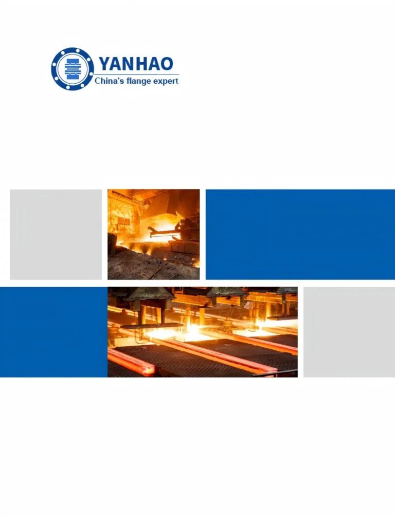
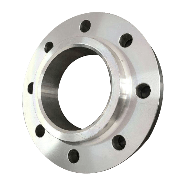
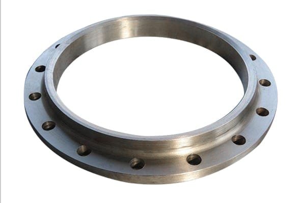
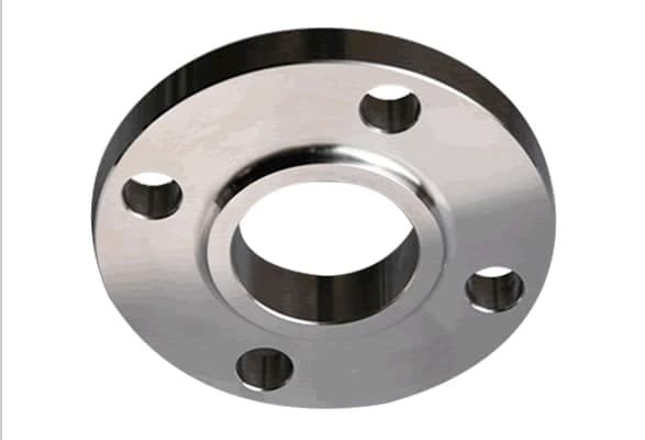
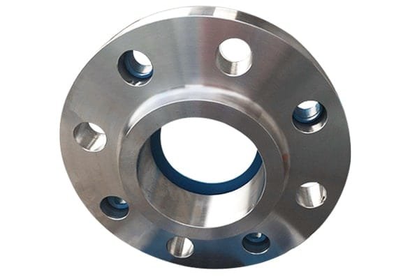
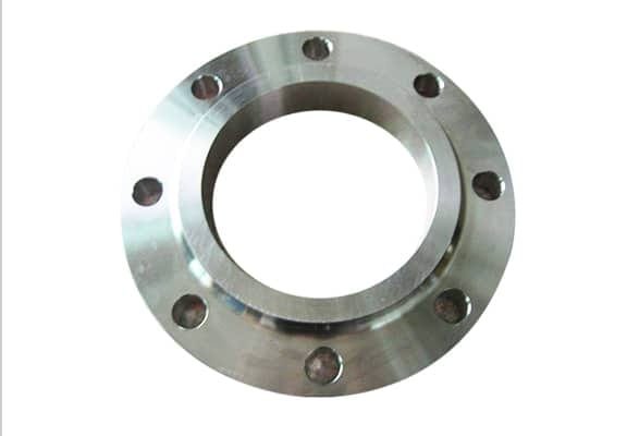
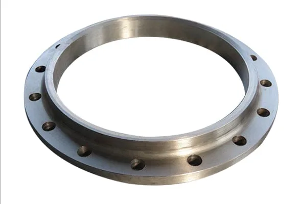
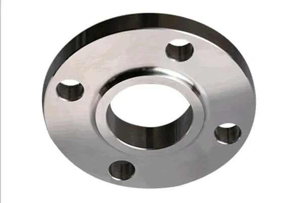
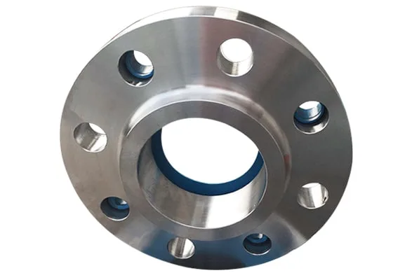
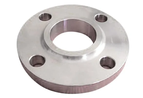
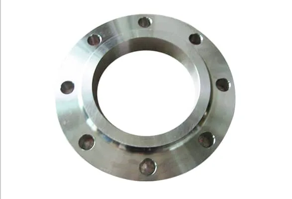
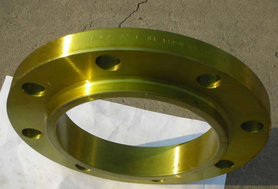
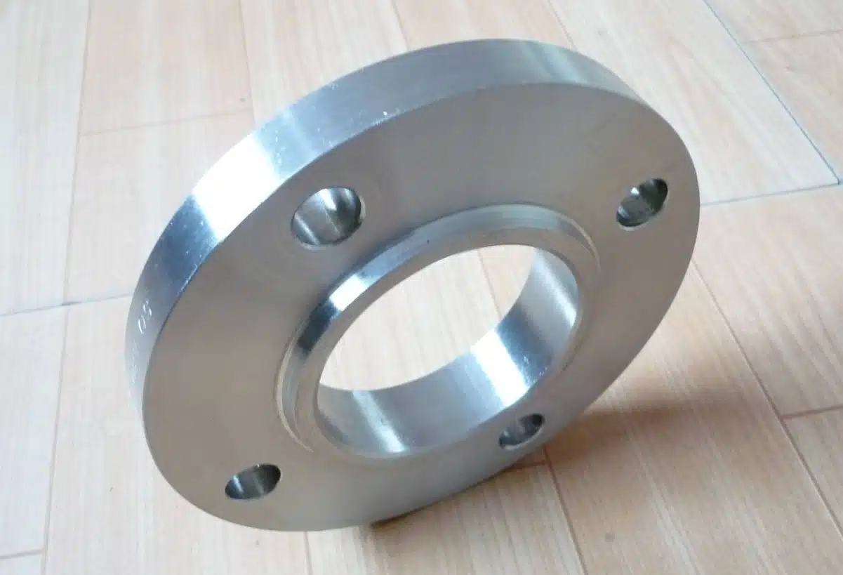
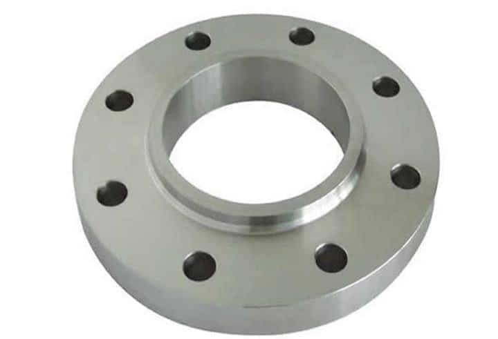
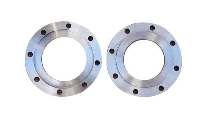
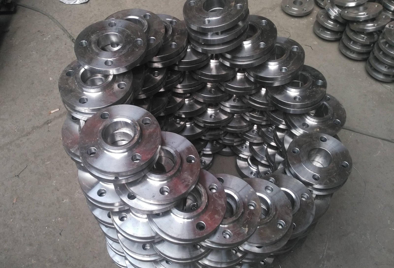
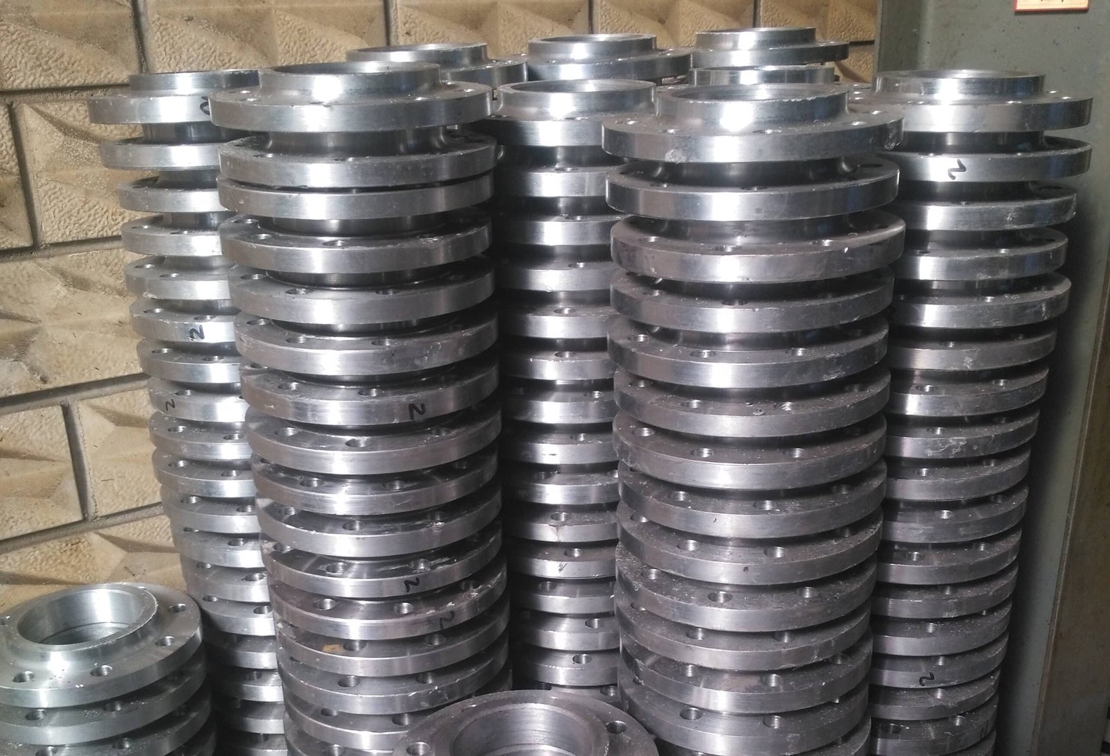
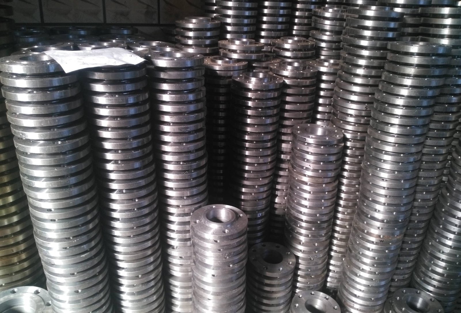
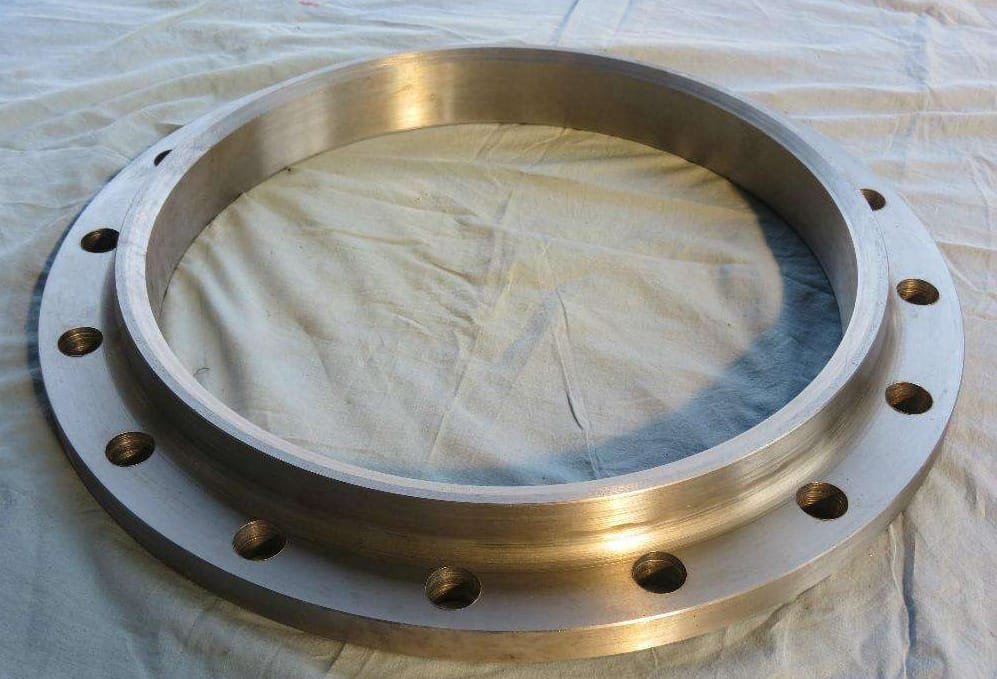
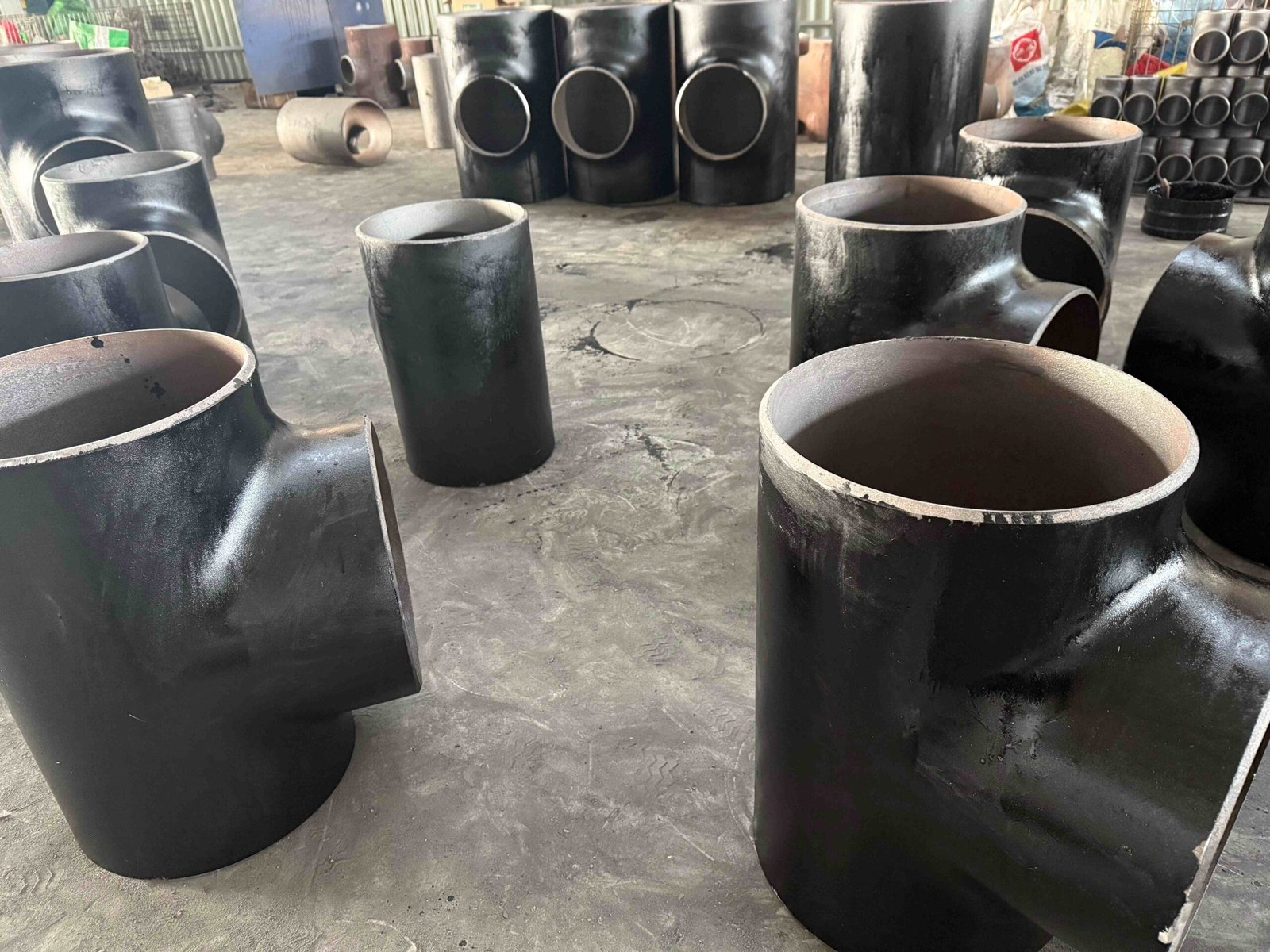
Here are various Slip-On Flanges produced by YANHAO. You can click on the pictures to enlarge them. As a company with 25 years of flange production experience, YANHAO supports all types of flange production.
Slip-On Flange Product Image Gallery
FAQs About Slip-On Flange

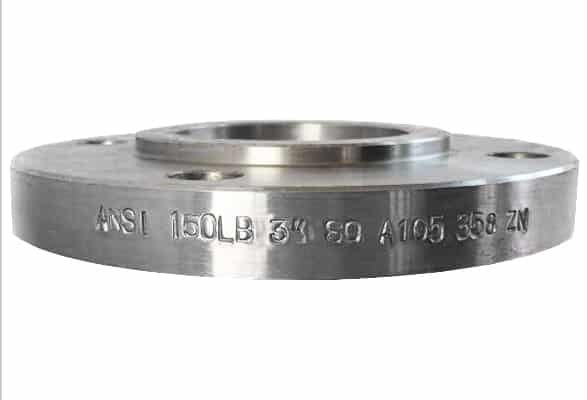
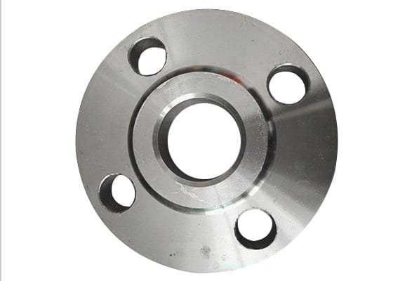
What is Slip-On Flanges?
Slip-on flange is a pipe connection fitting and a type of random flange. It is connected to the container or pipe through a fillet weld and is designed to be either integral or loose flange. The flange rings of slip-on flanges are of two types: with neck and without neck.
Compared with necked butt-weld flanges, slip-on flanges have a simpler structure and use less material, but their rigidity and sealing are slightly inferior to necked butt-weld flanges.
Slip-on flanges are widely used in the connection of medium- and low-pressure containers and pipelines.
Read More: Slip-On Flanges: Types, Uses, and Installation Guide
The slip-on flange (S/O flange) manufactured in accordance with ASME B16. 5 is a loose-type flange that has no direct connection to the adjoining pipe wall or the nozzle neck, or the vessel. It has a low hub that allows the flange to slip onto the pipe prior to welding.
slip-on flanges are mainly used for fluids at low pressure or with little risk of leakage. It is very common to find these flanges today in cooling water lines, firefighting water lines, low-pressure compressed air lines, and process lines for substances such as steam, oil, gas, condensates, etc.
B16. 5 is limited to flanges and flanged fittings made from cast or forged materials, and blind flanges and certain reducing flanges made from cast, forged, or plate materials. Also included in this Standard are requirements and recommendations regarding flange bolting, flange gaskets, and flange joints.
The American Society of Mechanical Engineers (ASME) and American National Standards Institute (ANSI) are important organizations in the flange industry. Each of them plays an integral role in developing the standards and codes that govern the industry.
The Weld Neck Flange offers increased strength under higher pressures, subzero or elevated temperatures that cause line expansion or retraction or other variable forces. The Slip On Flange is connected to the pipe by two welds, one on the back side of the Flange and one on the inside of the Flange.
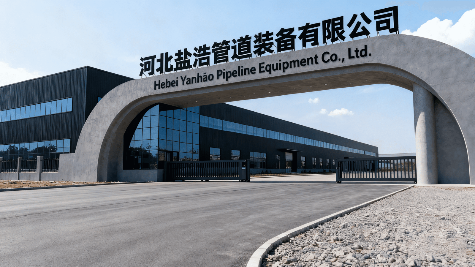
About YANHAO

YANHAO is a China Flange Manufacturer located in Hebei Province, China. It is one of the few professional Flange suppliers in China.
We have many years of experience in flange production and have multiple flange production lines. We have sufficient stock of raw materials, rich inventory, fast delivery, and can ship within three days. At the same time, the price is affordable. You are welcome to consult and purchase!
In addition, we can provide a variety of customized flanges and pipe fittings. Customers can give drawings or samples, and our company will produce them to fit your specific requirements.
Our company was founded in 2000 and has more than 300+ employees, including 85+ middle and senior engineering and technical personnel. Our company has several production lines and covers an area of 150,000 square meters and a building area of 30,000 square meters.
300+
Number Of Workers
85+
Mid&Senior Engineers
150,000
Square Meters of Area
25+
Years of Experience
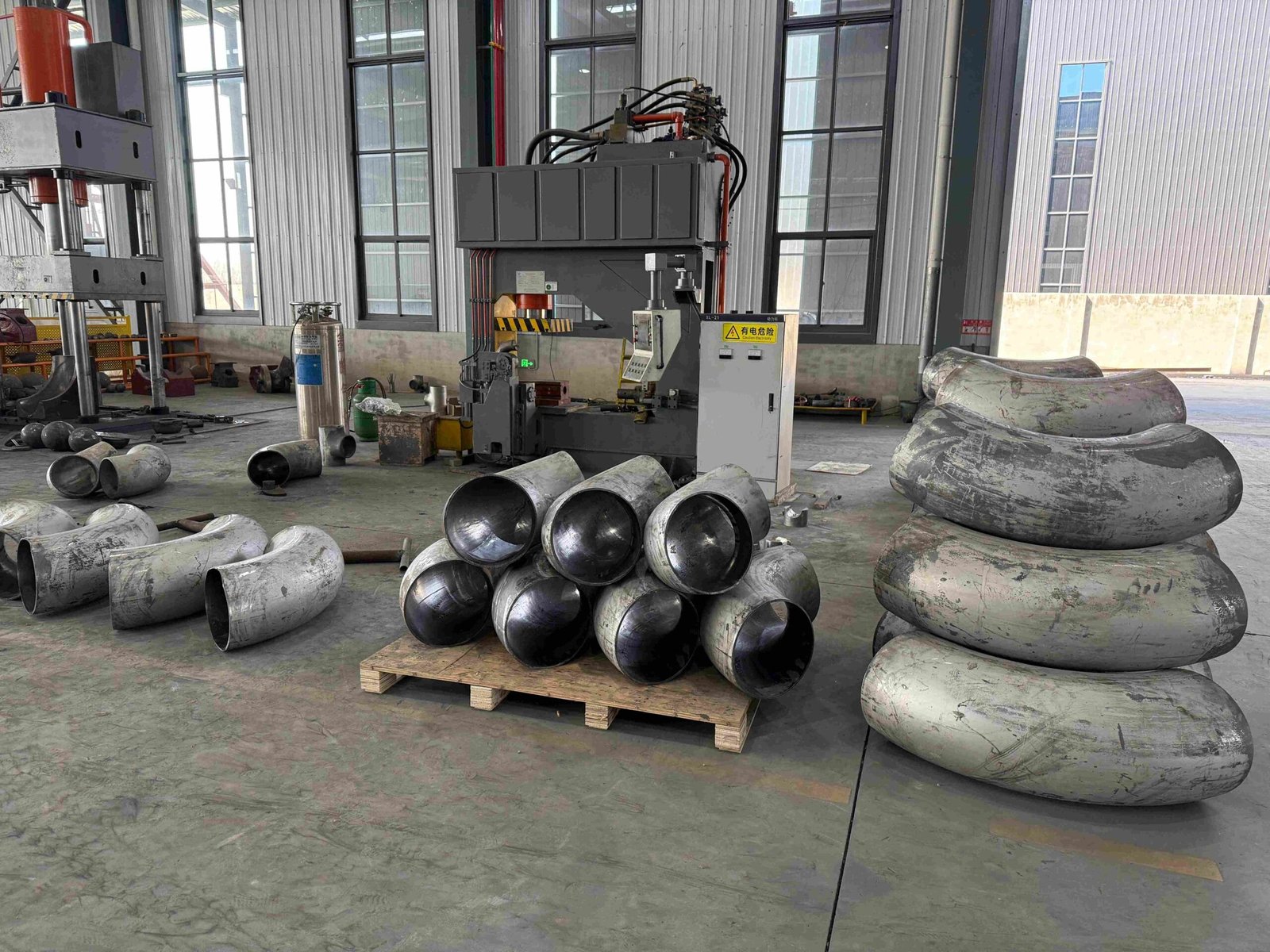
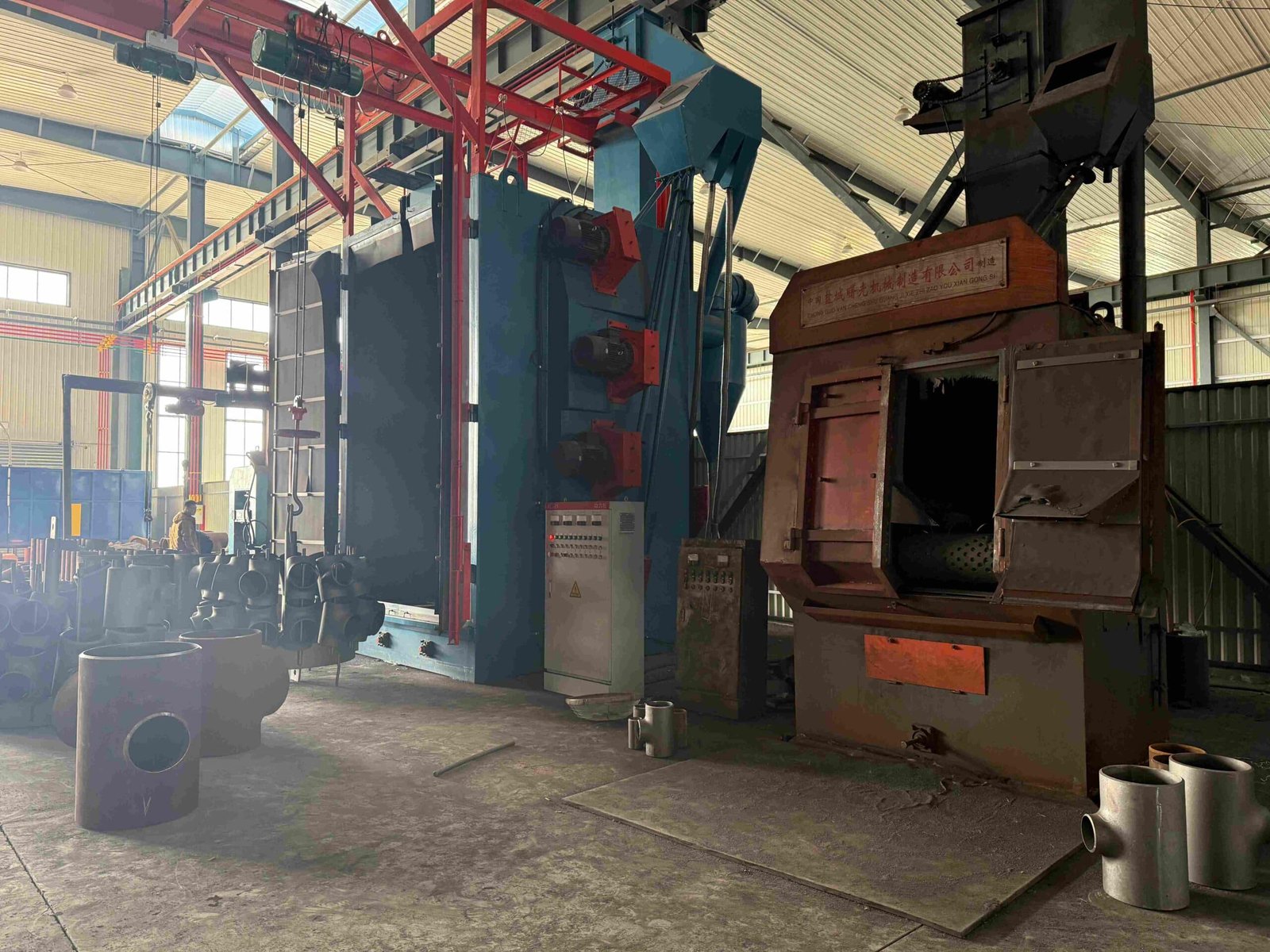
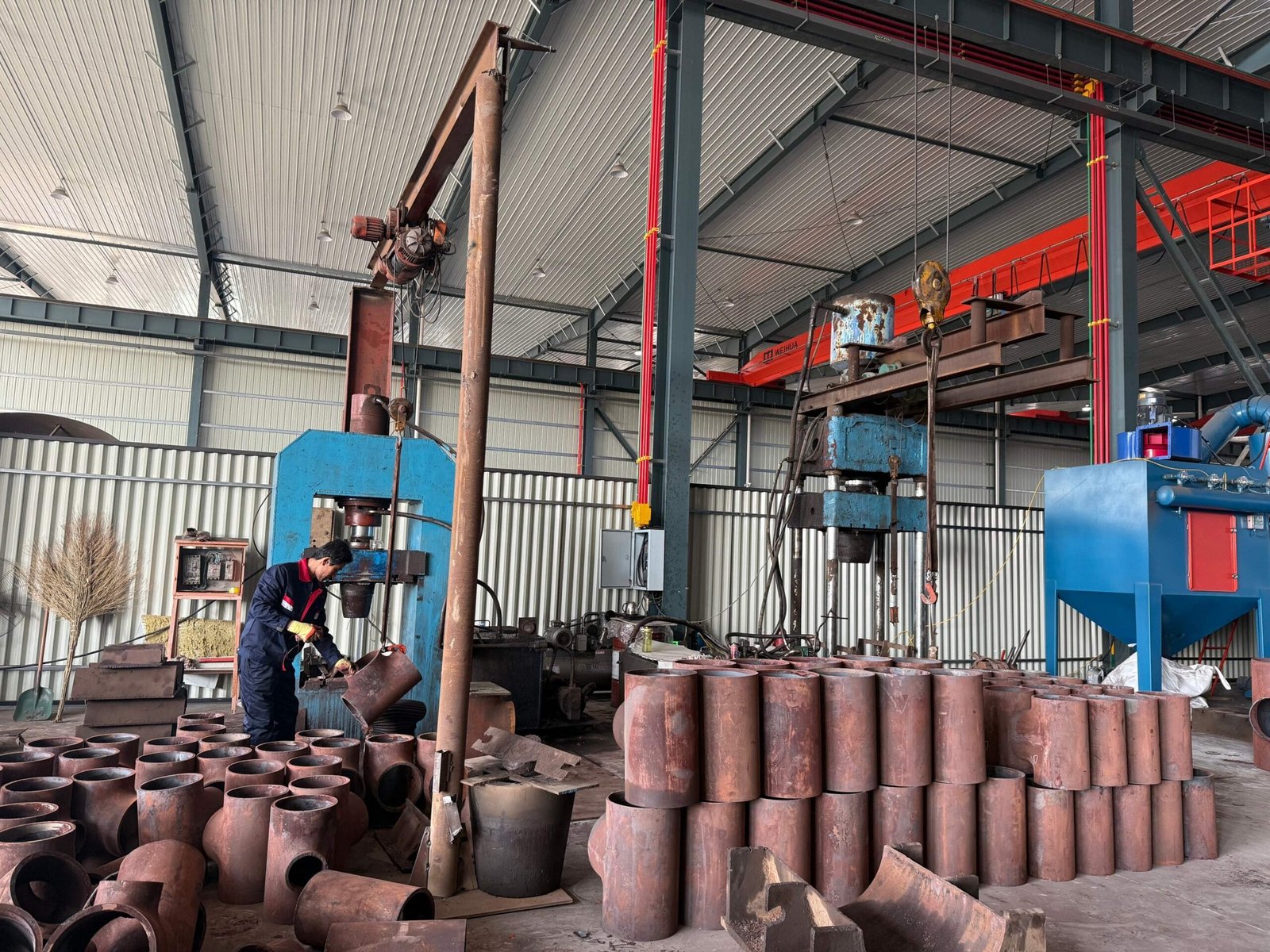
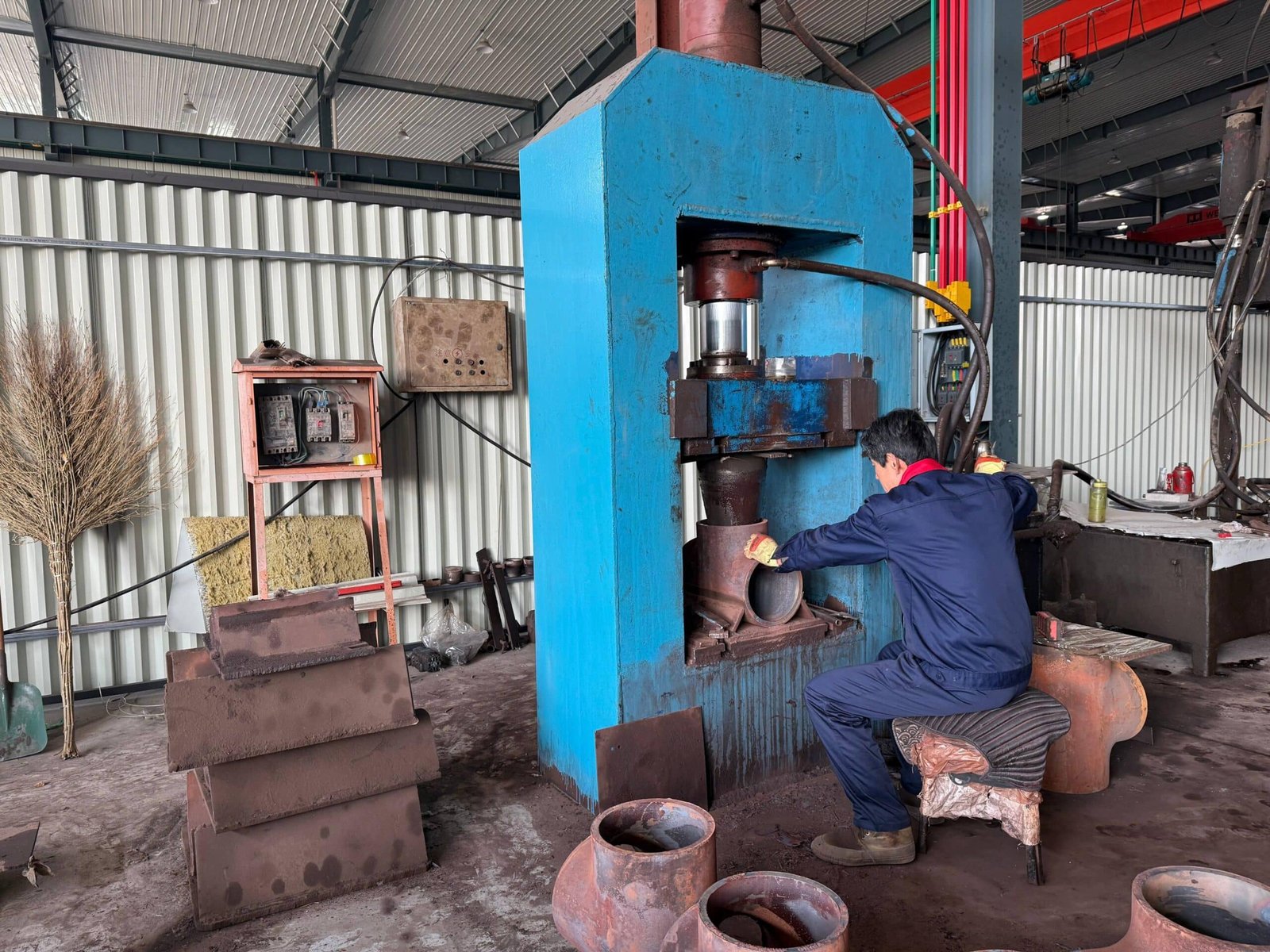
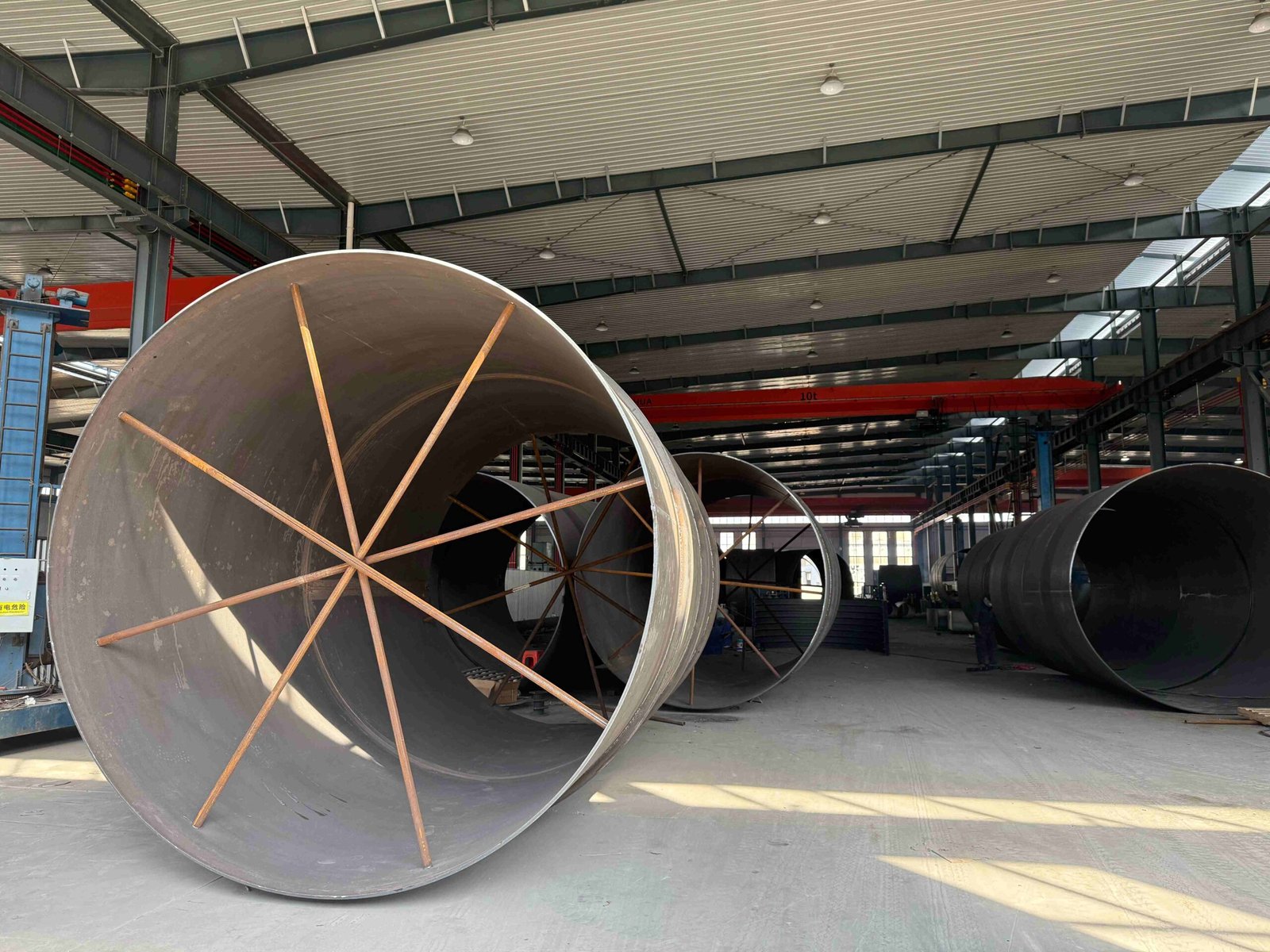
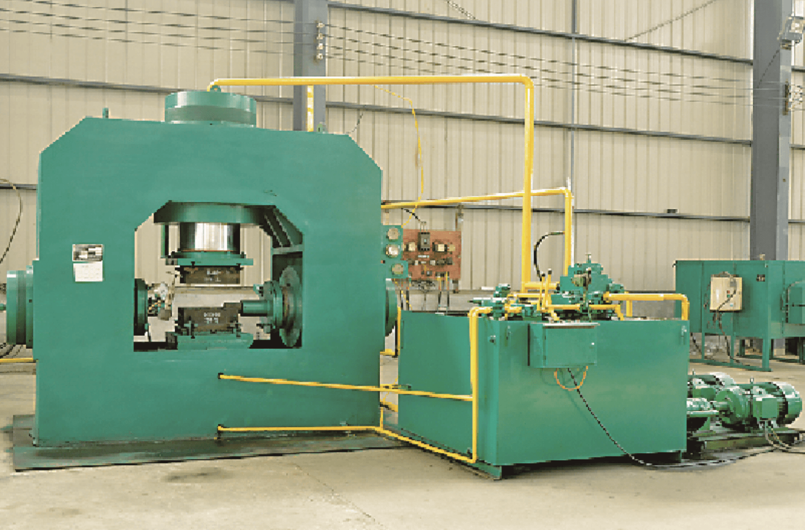
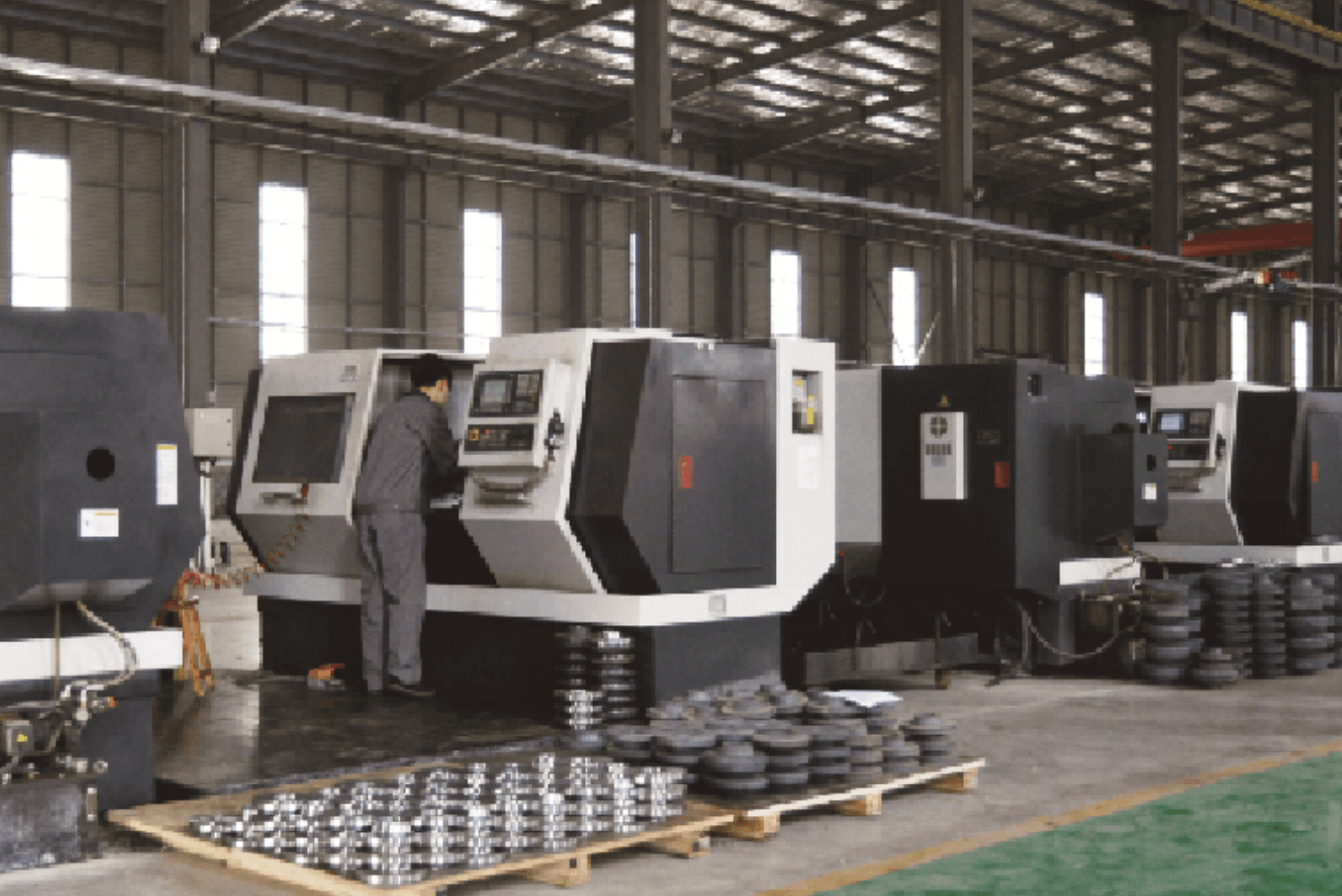
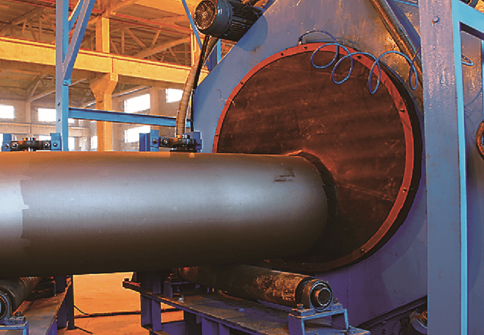
Our Production Line
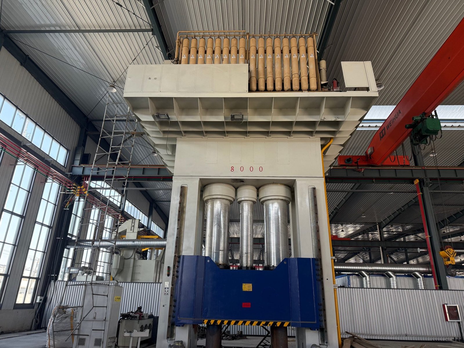
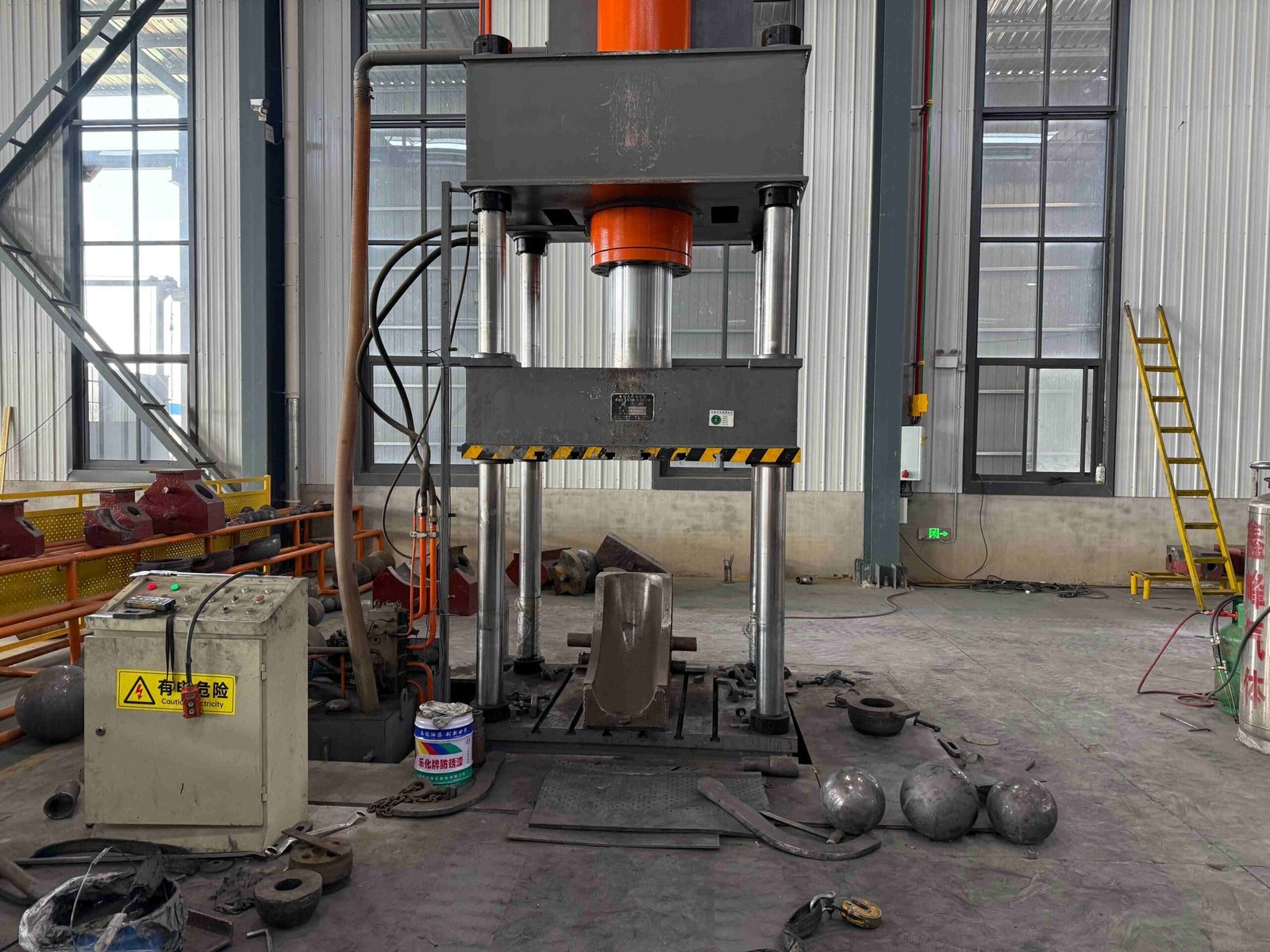
Our company has 8 pipe fitting production lines and 5 flange production lines. It has a full set of medium-frequency elbow hot-pushing machines, hot-die presses for reducers, cold-extrusion hydraulic presses for tees, forging hammers, vertical lathes, drilling machines, and other process-forming and mechanical processing equipment.
Among them, the Φ1020 mm large-diameter medium-frequency hydraulic pushing machine, Φ1420 mm large-diameter medium-frequency bending machine, and Φ2438 mm 4,000-ton large hot-die press have an annual production capacity of more than 80,000 tons.
8
Pipe Fitting Production Lines
5
Flange Production Lines
80,000 tons
Annual Production Capacity


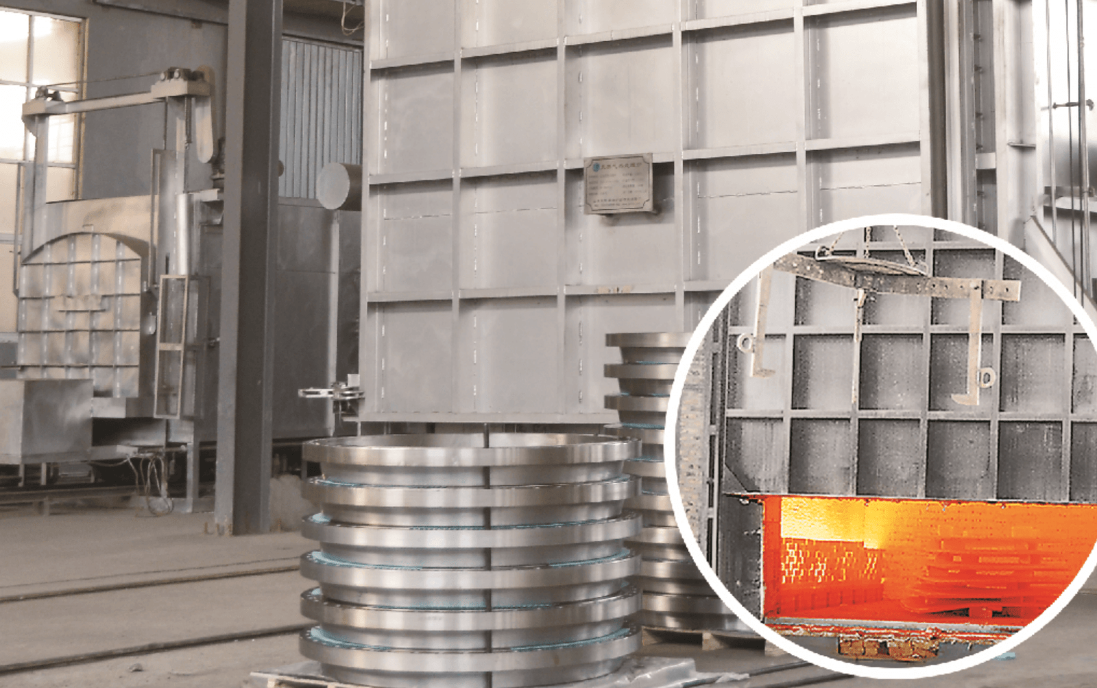
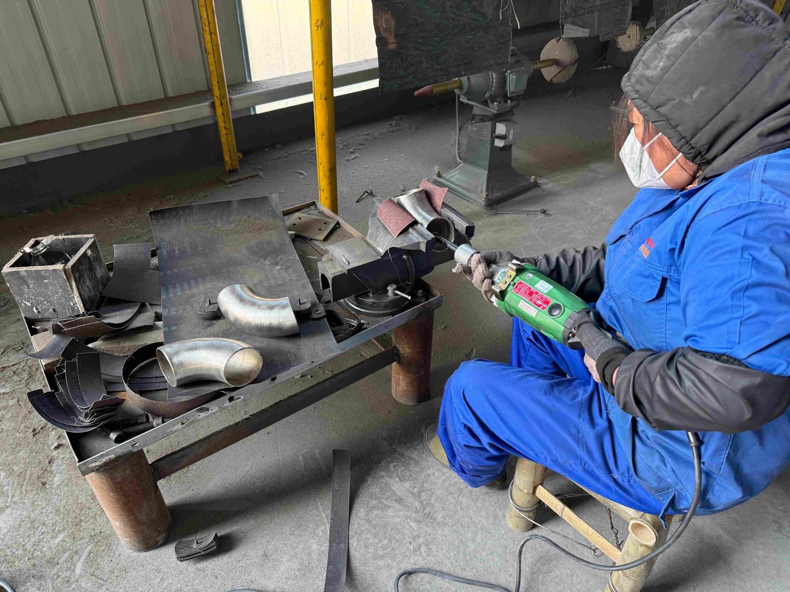
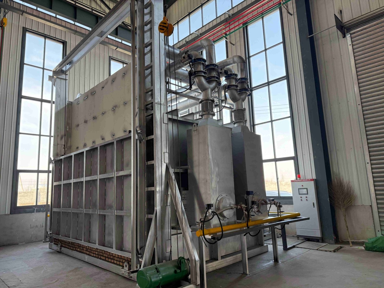
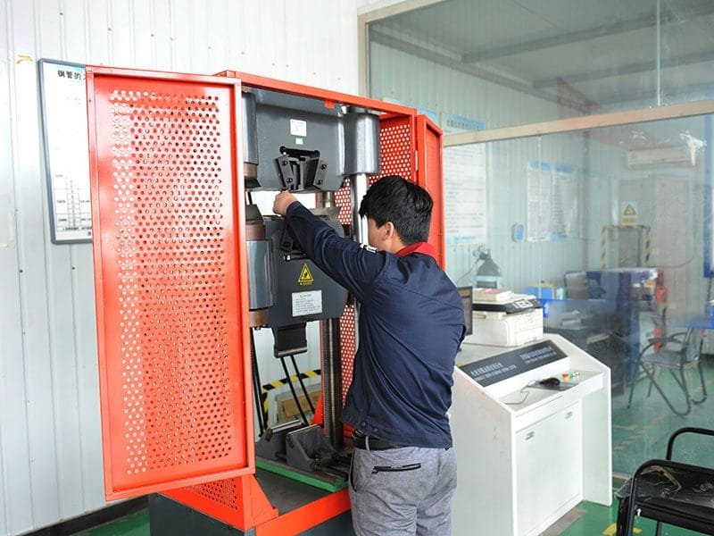
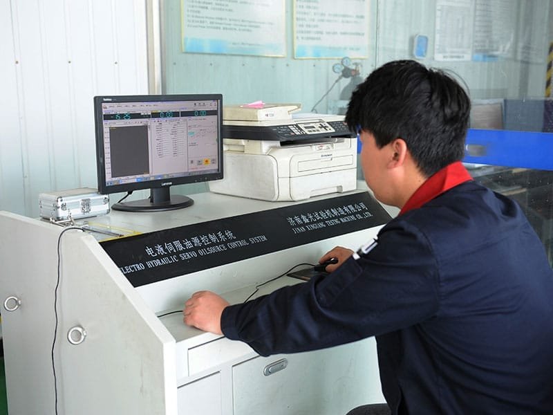
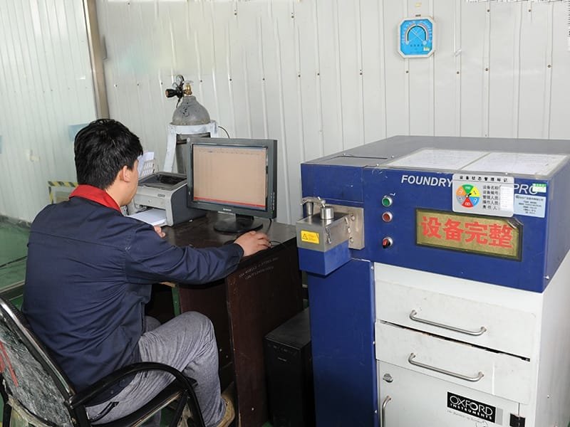
Quality Testing & Certificates
Our company is also equipped with a full set of physical and chemical testing, including spectrometer direct reading, non-destructive testing, heat treatment, water pressure testing, and other product quality testing equipment, providing a reliable guarantee for the production of high-quality products.


FAQs
Yes, we are a flange pipe fittings manufacturer located in Cangzhou, Hebei, China. Founded in 2000, we cover an area of 150,000 square meters, with a building area of 30,000 square meters. We currently have more than 300 employees and are a relatively large and powerful Chinese flange manufacturer.
The company has 8 pipe fittings production lines and 5 flange production lines. It has a full set of medium-frequency elbow hot push machines, reducer hot mold presses, tee cold extrusion hydraulic presses, forging hammers, vertical lathes, drilling machines and other processing and machining equipment. Among them, the φ1020 mm large-diameter medium-frequency hydraulic push machine, φ1420 mm large-diameter medium-frequency bending machine, and φ2438 mm 4,000-ton large-scale hot mold press have an annual production capacity of more than 80,000 tons.
For standard models, our factory has a large inventory, and the delivery time is usually only a few days. For non-standard parts, we also have a large reserve of raw materials and multiple production lines, which will save one-third of the time compared to other manufacturers and ship them to you as soon as possible.
We have our own testing system. Each batch of goods will have a corresponding product certificate and quality inspection report. At the same time, we have ISO9001 product quality certification, classification society certificate, ASNE quality certificate and other international authoritative quality certification certificates. We will never ship out unqualified products. In addition, we support customers to entrust third-party inspection companies for inspection and acceptance.
Of course, you can provide us with drawings or samples for customization, or you can ask us to design and customize your exclusive flange pipe fittings for you. Learn More>>
Our products are used in oil, gas, chemical industry, machinery, shipbuilding, aerospace, electricity, pharmaceuticals, construction engineering, water conservancy engineering, and marine engineering. Don’t worry about some special fields with high requirements. We have strong production capacity and rich production experience and can provide you with professional solutions. You can send us your working conditions and we can give you a solution for free.
Our company can provide you with samples for free, you can contact sales to request samples.
Of course, you are very welcome to visit our factory. We will also arrange meals and accommodation for you. If you have enough time, we can also take you to visit China’s famous mountains and historical sites, so that you can better understand China and our culture. It will be worthwhile and we look forward to seeing you.
Middle Eastern customers visit Yanhao pipe fittings factory
We are the source manufacturer. If you have the strength, you will get more favorable prices, faster delivery and more guarantees if you purchase directly from us. We will have professional sales staff to track customers’ orders throughout the process, update the order status in real time, and let customers know their order progress and product quality in real time.
We support payments in over 40 currencies worldwide.
We have a long-term logistics transportation company that supports sea, land and air transportation to ensure that customers receive the goods on time. At the same time, if customers have a cooperative logistics company, we will still fully cooperate with your logistics company to ensure that customers can receive the goods as soon as possible.
More Types of Flanges

Weld Neck Flanges (WN)
WN flange, also known as a trapped hub flange or high-hub flange, is a high-stress-containing flange.
Slip-on Flanges (SO)
Slip-on flanges, as the name shows, can be easily slipped onto the end of a pipe or fitting and then welded in place.

Socket Weld Flanges (SW)
Socket Weld Flanges (SW) are similar to Slip-on Flanges (SO). The difference is that there is an extra piece in the middle.

Blind Flanges (BF)
Blind flange is also called flange cover. It is a flat, circular plate used to cover the ends of pipes, valves, or joints.

Lap joint flange (LJ)
Consisting of two components: a stub end and a lap joint ring flange. The respective stub end is slid into the flange’s bore, and the stub end is joined to the pipe through butt welding.

Threaded Flanges (TF)
Threaded flanges are pipe flanges with internal threading to match external threads on a pipe.